Belimo Energy Valve Manual
Http Www Kele Com Catalog 04 20control 20valves Pdfs Ev 20technical 20documentation Pdf
Http Www Belimo Cl Dinamicos Productos Energyvalvetechdoc Pdf
Http Www Primeent In Wp Content Uploads Woocommerce Uploads 2017 11 Energy Valve Product Spec Pdf

Ev300su 180 Arx24 Ev Belimo Energy Valve Control Products
Https Alpscontrols Com Prod Data Newdocs Belimo Energyvalvetechdoc Pdf

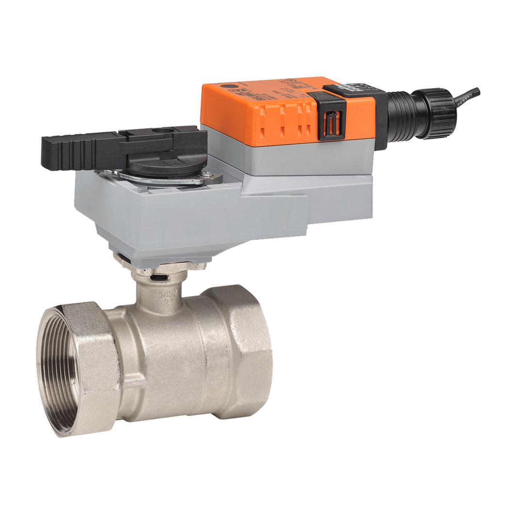
Ev200s 761 Arx24 Ev Belimo Energy Valve Control Products

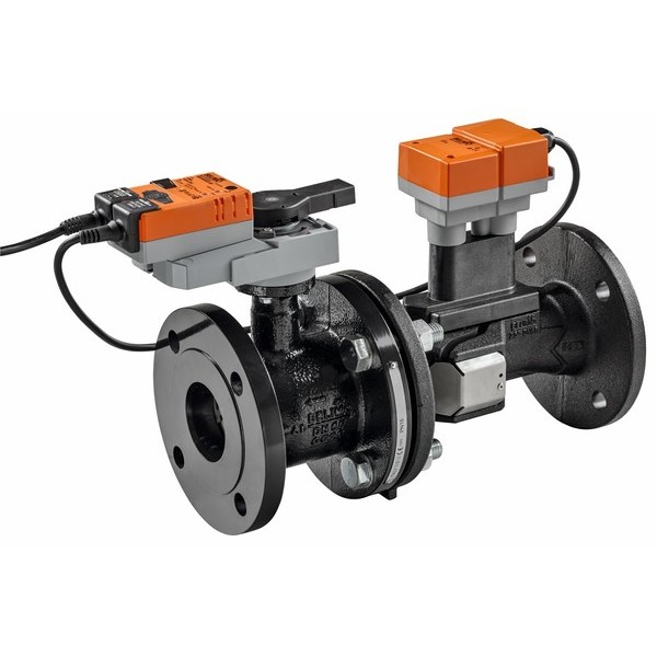
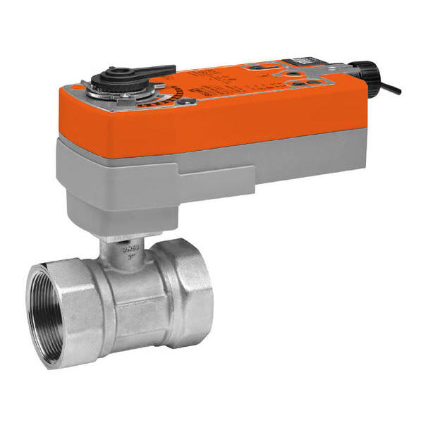
The energy valve is recommended to be installed on the return side of the coil.
Belimo energy valve manual.

Ev250s 127 Akrx24 Ev Belimo Energy Valve Mercato Bas Supply

Ev032r Bac Electr 2 Way Pi Ccv Belimo Energy Valve
Http Www Wasbo Com Images Wasbo Documents 6 Handouts Mfm2015 Pressureindependentvalvetechnologiesandbenefits Binder Pdf

Belimo Energy Valve Technical Documentation Pdf Free Download

Ev400s 317 Gkrb24 Ev Belimo Energy Valve Control Products
Https Www Belimo Com Mam Americas Technical Documents Data Sheets Water Ev300s 180 Arb24 Ev Pdf

Energy Valve 3 0 Youtube
Https Www Belimo Com Mam Americas Technical Documents Data Sheets Water Ev125s 285 Nrb24 Ev Pdf

Belimo University 2012 All Rights Reserved Pressure Independent Control Valves Piccv Epiv Energy Valve Belimo S Family Of Pi Control Valves Flow Verification Commissioning Ppt Download

Pressure Independent Valves Belimo
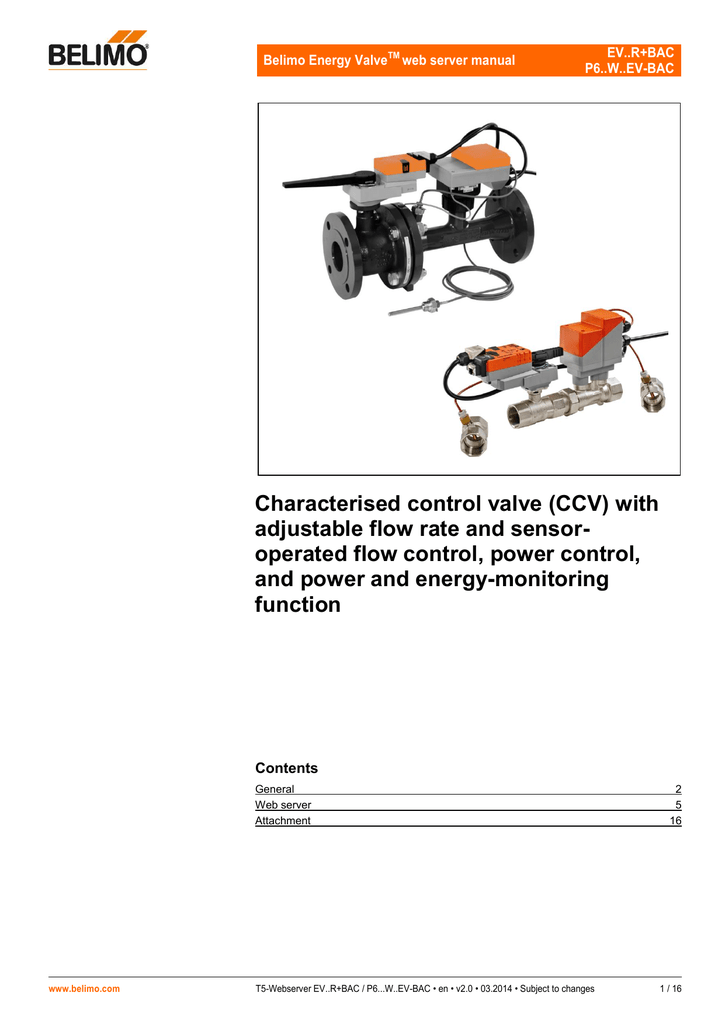
Characterised Control Valve Ccv With Adjustable Flow Rate And
B223 Lrb24 Sr Boston Aircontrols
P6500su 495 250 Grx24 Ep2 Boston Aircontrols

Belimo Energy Valve Webinar Youtube

Belimo M2420 Ev 3 4 Energy Valve Flow Sensor Blackhawk Supply
Actuators Valves And Sensors Belimo
B254 Afrxup Boston Aircontrols

Ev200s 761 Akrx24 Ev Belimo Pressure Independent Valves

Zone Valves Belimo
F6250 300shp Sy4 24 Boston Aircontrols

Belimo Tech Tips For Characterized Control Valves Ccv Youtube
F665 300shp Prbup Mft T Boston Aircontrols
Actuators Valves And Sensors Belimo Pressure Independent Valves

Webinar Belimo Fire Smoke Damper Actuator Replacement Instructions Youtube
Source : pinterest.com
